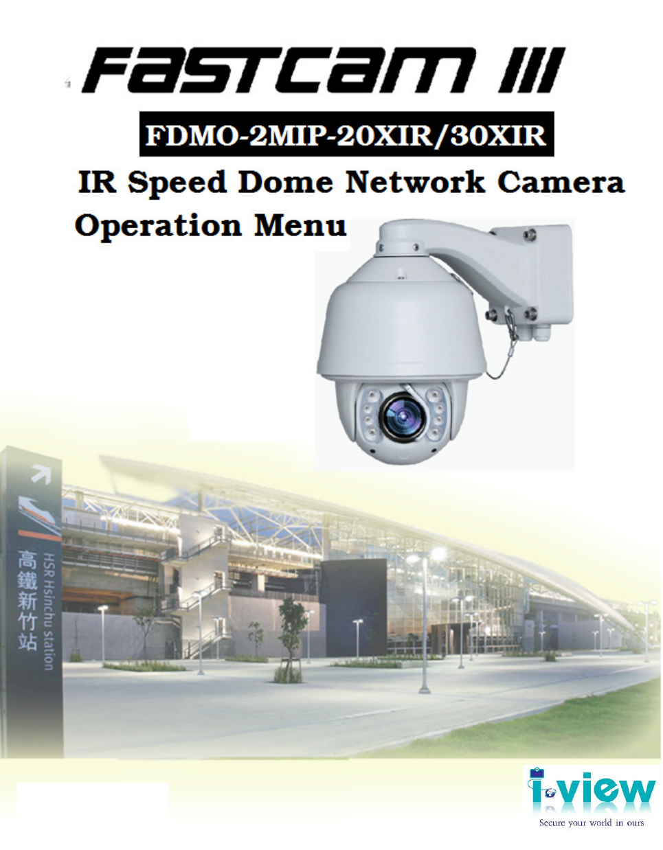
I-view FDMO-2MIP-20XIR IP SpeedDome Network Camera Manuel d'utilisateur
Naviguer en ligne ou télécharger Manuel d'utilisateur pour Caméscopes I-view FDMO-2MIP-20XIR IP SpeedDome Network Camera. I-View FDMO-2MIP-20XIR IP SpeedDome Network Camera User Manual Manuel d'utilisatio
- Page / 90
- Table des matières
- DEPANNAGE
- MARQUE LIVRES
- Version: V1.0 1
- Doc. No: 2014021601 1
- Safety information 3
- 1. Features 8
- 1.5 Function Instructions 9
- 2. Technical Specifications 13
- 2.2 Packaging Contents 16
- 2.3 Product Dimension 16
- 2.4 Cable Description 17
- 3. Installation Guide 18
- 3.2 Installation Procedures 19
- 3.3 Network Deployment 21
- 5.3 Operation Instructions 34
- 6. OSD Menu Functions 57
- 7. Troubleshooting 90
Résumé du contenu
Version: V1.0. Doc. No: 2014021601
9 The dome can store up to 220 presets. Auto Scan Users can set up the left and right boundaries by control keyboard. Then speed dome can scan
10 Coordinates and Directions Display User can define the dome’s direction of due north, which will help to show up the exact moving directions
11 Note: This feature varies depending on speed dome models. Power On Memory The dome supports the power on memory capability with the predefin
12 2. Technical Specifications 2.1 Specification Camera Image Sensor: 1/2.8’’ SONY Exmor™ CMOS sensor Effective Pixels: 1920(H)x1080(V) Signal
13 (Vair-speed) Preset Speed 360 o/S (high speed) / 35o/S (Vari-speed) Presets Number/Accuracy 220 / +/-0.1o Guard Location The dome will rotate
14 60Hz: 30 fps (1920×1080), 30 fps (320x240) Image Compression: H.264 Baseline/Main/High profile; MJPEG ROI encoding: Support 5% areas of image
15 2.2 Packaging Contents Please check the contents of your new Network IP Speed dome Camera when you unpack the package. The package includes
16 2.4 Cable Description 1) Network port: Plug the RJ-45 LAN cable. The Green LED on for power OK; Green LED flash for communication
17 3. Installation Guide 3.1 Specification Installation Method The IR speed dome could be installed in wall-mount and pedant-mount Wall Mount
18 3.2 Installation Procedures Wall-mount Installation Procedures: 1) Take out the bracket from the package (as shown), mark the installation hole
1 Table of Contents 0. Safety Information …………………………………………………...2 1. Features ……………………………………………………………….7 1.1 Main Features ……………………………………………
19 2) Drill the hole and install 4 pieces of M8 expansion bolt into the hole. 3) Take out the IR speed dome and put the cables through
20 3.3 Network Deployment General Connection (without PoE) 1. Connect RJ45 Ethernet cable to a switch. Use a Category 5 Cross Cable when
21 4. Running IP Camera by Witness Pro NVR software 4.1 Install Witness Pro NVR software You can use your new Network IP Camera by its web user
22 4.2 Setting IP camera for Witness Pro NVR software Click “ Start “ >> “ All Programs” >> “Witness NVR32 Pro”, then select the “ Vid
23 compliant and not on the list. You can check the used camera support Onvif compliant from: http://www.onvif.org. Click “ Onvif setup “ icon
24 The difference IP camera brand has its own “Find” and “Advance setup” setup diagram and setting process. For the detail information, please ref
25 5. Running IP Camera by I.E. Browser You can use your new Network IP Camera by its web user interface via I.E. web browser. The requirements
26 Step 2. Press “Search “button to search for all IP Cameras on your local network. Step 3. If you need to change IP address, double click
27 If you connect to IP Camera first time, you’ll see the following message; this message prompts you that you need to install ActiveX plug-in bef
28 IE 10 version: Click ‘Install’ button located at the bottom of I.E. to install ActiveX plug-in. You need to do the process as below: Click
2 Safety information This symbol indicates that dangerous voltage consisting a risk of electric shock is present within this unit. This
29 5.2 The Function Description of Live Window After ActiveX plug-in is installed, you should be able to see the live video from IP camera as bel
30 again will stop recording. The default path is C:\WebData\record. 6. Screen: Display video of IP camera on the screen. 7. Screen: Choice t
31 Setup the Preset, Tour, Scan and Track function: Setup Preset position: 1. Move the IP speed dome Pan/Til
32 Setup Tour : 1. Select Tour ID and then entry the Tour name. 2. Drop the menu from the Type section, and then select the Tour item. 3
33 5.3 Operation Instructions 1) Main Functions Fast Call Table Our IR IP Speed dome supports 220 preset positions. You can activate some special
34 3) OSD Menu Operations Call Preset 95 to enter the main OSD menu (or call preset No.1 two times continuously within two seconds). Control th
35 5.4 The Network setup Function Description Click “Setup “ icon to start setup the parameters of IP camera. You can configure basic IP camer
36 IP Property: Click this button to modify the current Internet protocol with IPv4 or IPv6, IP address, enable/disable DHCP and DNS IP address.
37 Device Port: If there is a router and you want to access the speed dome through Wide Area Network (WAN), you need to forward the 3 ports for
38 Timing: Click this button to setup the time of IP camera. The detail process description as below: Time Zone setup:
3 6. Do not place conductive objects (e.g. screwdrivers, coins, metal parts, etc.) or containers filled with water on top of the camera. Doing
39 save the settings. You can also click the Save icon with computer time checkbox to synchronize the time of the IP Camera with the time of your
40 2. Click Edit icon to select the Protocol and then entry the Internal/External Port. 3. Click Add icon to increase this port. Repeat the 1
41 SMTP: The system can be configured to send an Email notification to all designated receivers if an alarm event is detected, e.g., motion det
42 code into your mobile App, then you can remote viewing /Recording the IP camera video and also can control the PTZ IP camera. .
43 Streaming: Configuring Video streaming settings as below: The RTSP command code as below: Main streaming: RTSP://IP Address:554/media/live
44 Quality: hen bitrate type is selected as Variable, 9 levels of video quality are selectable. The higher will get better video quality, but
45 Flickless: Set the Video Standard to 50hz(PAL) or 60hz(NTSC) according to the video system in your country, Wrong frequency will show the scr
46 OSD: Allow to paste text (Device name) and time stamp on the video. Basic setup: You can choice the font size and transparency for th
47 Privacy Mask: Privacy mask enables you to cover certain areas on the live video to prevent certain spots in the surveillance area from being
48 I/O & PTZ setup: You can setup the alarm input/output and PTZ protocol from this section. PTZ: Setup the PTZ parameter
4 IMPORTANT SAFETY INSTRUCTIONS Read these instructions. Keep these instructions. Heed all warnings. Follow all instructions. Do no
49 Alarm Trigger: You can setup the image motion trigger and sensor alarm trigger from this section. The detail process show as below:
50 Motion alarm: Enable Motion detection function and you can setup the trigger schedule and detection area. Click and drag the left button
51 recording at 10:00, and the pre-record time is set as 5 seconds, the IP Camera starts to record at 9:59:55. Post-record: The time you set to
52 Record path: Select the recording media via FTP server or SD card. To configure record settings, please make sure that you have the net
53 Authority: Setup authorized users and group from this section. Group: Define the privilege of Group user, there are th
54 Maintenance: Click this button to update the firmware, restore the default setting and check the view log …etc. Please refer the detail
55 “ icon the IP camera setting become to default. Clicking Reset icon will restores all the parameters to default settings including the IP add
56 6. OSD Menu Functions
57 LANGUAGE The language for the on-screen menus is Selectable. To change the display language: Press Iris Open to enter selection. All o
58 SYSTEM INFORMATION The user can check the dome system information as required. The system information includes: Dome ID, dome address, baud
5 SAFETY INFORMATION FCC STATEMENT This device complies with part 15 of the FCC Rules. Operation is subject to the following conditions: This d
59 DISPLAY SETUP Display setup allows the user to define the way to display the dome titles on the monitor. The displayed titles are l
60 IR LED The user can open and close the IR LED manually and set up the IR LED work mode under this OSD mean. (Under normal operation
61 status. 7) SENSITIVITY: When the AUTO CONTROL is on, the user can set up the sensitivity to detect the moving objects. 8) ENHANCE
62 IDLE IDLE setting means if there is no command for the dome for a period of time, the dome will run the actions as defined. 1) TIME: Move
63 3) ALARM The dome system has 2alarm inputs and 1 alarm output. (Option0. When an alarm is received, an input signal to the dome triggers the
64 PRIVACY MASK Privacy mask allows the user to mask the privacy areas with black frame. The user can set up 8 privacy masks at most.
65 CLOCK The dome can display the data and time. And the user could enter this CLOCK menu to set up the DATE and TIME. DATE: Move the curso
66 PASSWORD The dome features password protection function to prevent unanthorized changes to the dome settings. If the PASSWORD
67 DOME TITLE The user can set up the dome title to define each camera. Dome title support up to 12 characters. Move the cursor
68 SOFT ADDRESS SET The use can set up the SOFT ADDRESS, SOFT PROTOCOL and SOFT BAUD RATE under this menu here to activate the s
6 About This Guide Conventions used in this guide To make sure that you perform certain tasks properly, take note of the following symbols to use
69 AUX The user can set up the auxiliary output to trigger other devices from an alarm or a controller. Move the cursor to AUX
70 SOFT LIMIT The user can set up the soft limit to define the left and right boundaries for the pan move
71 DOME SPEED To make a selection of the dome speed, the user can enter this menu to set up. Move the cursor to DOME SPEED and press
72 POWER ON ACTION The user can define the dome action when power on, Move the cursor to POWER ON ACTION and press IRIS OPEN t
73 CAMERA The dome can automatically recognize the main camera modules in the market. For the cameras it cannot recognize, the u
74 COMMUNICATION TEST The dome can do self diagnosis for the communications between keyboard and speed dome. The test needs to matc
75 OTHERS The user can set up TEMP MODE, INTERNAL FAN, PRESET FREEZE, STOP TIME. MENU OFF TIME and NORTH ZERO here under th
76 CAMERA The user can make adjustment for the cameras under this menu. FOCUS MODE: AUTO FOCUS allows the camera lens to remain in
77 CAMERA ADVANCED The use can set up more detailed parameters of camera here under the menu of CAMERA ADVANCED. WB: To set
78 PRESET The dome supports 220 presets. Please check the following steps to set up a preset. 1) PRESET NO.: Move the cursor here and
7 1. Features 1.1 Main Features 1080p HD SONY Exmor CMOS Sensor. 30 fps @ 1080p Full HD. 20x Optical Zoom Lens and 12x Digital zoom; tot
79 AUTO SCAN The dome supports 8 groups of auto scan. Please check the following steps to set up a scan. 1) SCAN NO.: Move the cu
80 AUTO CRUISE (SEQUENCE) The dome supports 8 groups of auto cruise and each cruise supports 32 presets. . Please check the following s
81 PATTERN TOUR The dome supports 4 pattern tours and each pattern cover at most 10 Minutes of 500 commands. Please check the fo
82 ZONES The use can set up zone title when the camera moves to a defined location, which will make it much easier for the
83 TIMING ACTION TIMING ACTION allows the user to set up the actions of the dome in 7 days (each day with 8 timing segments)
84 MOTION DETECT The user can set up 8 motion detection scenes (each scene with 4 detecting areas) under this menu. The alarm
85 the detecting function, for how long it will last before the aux output will be closed. The time ranging 1-60 Sec. h) START: Move the cursor h
86 AUTO TRACKING (Optional) Under the auto tracking mode, the dome will auto track the moving objects entering the scene. When t
87 RESTART The dome allows the user to reset its settings remotely under this menu. Move the cursor here and press IRIS OPEN
88 FACTORY DEFAULTS FACTORY DEFAULTS will allow the user to recover all the setting to factory default setting. Move the cursor here
8 1.2 Integrated Super Speed PTZ Rotator Delicate stepping motor, stable, sensitive and accurate 360° Pan and 90° Tilt range (auto-flip) wit
89 7. Troubleshooting Before you send this IP Camera back to your dealer when you found this IP Camera is not working properly, please chec
Produits connexes et manuels pour Caméscopes I-view FDMO-2MIP-20XIR IP SpeedDome Network Camera
 (55 pages)
© 2020, manymanuals.fr. Tous droits réservés | 0.854 s |
 Manymanuals.com
 Manymanuals.de
 Manymanuals.fr
 Manymanuals.it
 Manymanuals.pl
 Manymanuals.cz
 Manymanuals.es
 Manymanuals-pt.com
Commentaires sur ces manuels